Sega Genesis/Mega Drive Joystick to USB HID Joystick
When I first started messing with electronics a few years ago and got my first cheap Arduino Uno clone, one of the first things I did after getting an LED to blink was trying to read input from a Sega Genesis controller, by soldering wires into a DE-9 connector and plugging it straight into the Uno. This taught me a lot of things, like active high vs. active low, using the serial monitor to debug, and that the Uno form factor is kind of a hassle for anything more complicated than blinking an LED. A couple years later, I started playing with development boards like the Digispark and Arduino Micro that are capable of presenting themselves to the computer as USB devices with minimal effort, and decided to see if I could get a Genesis controller working as a PC joystick.
Three-button Genesis controllers are pretty simple to read, but not quite as simple as an Atari 2600 joystick despite using the same connector, because there are more signals to send (8) than the connector has free pins (7). Sega solved this problem by using a multiplexer to assign two signals to each pin, and then toggle between them by setting the Select pin high or low. Only two of the buttons (A and Start) need to be read with Select low, the rest can be read while it's high. DE-9 connectors are cheap and easy to find, and the controller has internal pull-up resistors so all you need to do is connect the pins.
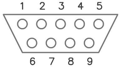
DE-9 connector, console (male) end
| Pin | Function | Select LOW | Select HIGH |
|---|---|---|---|
| 1 | Up | Up | Up |
| 2 | Down | Down | Down |
| 3 | Left | GND | Left |
| 4 | Right | GND | Right |
| 5 | +5V | ||
| 6 | A/B | A | B |
| 7 | Select | ||
| 8 | GND | ||
| 9 | Start/C | Start | C |
That's all there is to it. To read input with a microcontroller, just connect pin 7 as an output and pins 1/2/3/4/6/9 as inputs. Set the Select pin low and you can read Up/Down/A/Start, set it high and you can read Up/Down/Left/Right/B/C. If your microcontroller of choice doesn't have seven pins free (like on a Digispark, which only has four since the USB connection needs two of them), you can also get by with four total pins by connecting the Select pin straight through and running the rest of the signals through a shift register like the CD4021 — there's a tutorial here on the Arduino site. One thing to note if you're using a Digispark: if you're using one of the clones readily available online for next to nothing, there may not actually be four pins available if the reset pin hasn't been properly configured to act as an I/O pin.
Here's some example code for reading a three-button Genesis controller on a Digispark Pro and its included USB joystick library. Using an Arduino Micro or some other platform instead is just as simple, just swap out the joystick library and pin mapping as necessary. The choice of pins doesn't matter at all, in the example I just picked whichever pin was easiest to reach at the time.
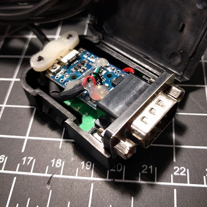
Once I got the prototype working, I decided to do something uncharacteristic and actually finish the project instead of just leaving it sitting on a breadboard for eternity. For me, that would normally mean messily wiring it up on a proto board and just leaving it to flop around exposed on my desk, but a quick eBay search turned up some DE-9 connector enclosures that I could re-purpose for the project and make it look slightly more professional. I bought one and desoldered the terminal blocks, then just ran solid core wires from the breakout up through the pads on a Digispark Pro and squashed as flat as possible before soldering it all together. The original plan was to line up the micro USB connector with the hole in the end of the enclosure, but it proved too small to fit a plug through, so I directly soldered in a USB cable salvaged from an old mouse. I didn't consider at the time that this meant the resistors on the USB data lines were now totally bypassed. Fortunately for me, despite the USB specifications being rather strict about what you can and can't do, in reality you can just do whatever the hell you want and it still works fine. I probably should go back in and fix it sometime, but probably won't.
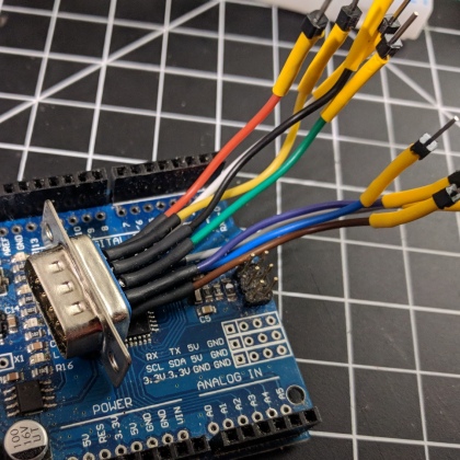
The awkward octopus used for the original prototypes
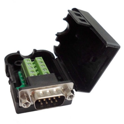
The DE-9 breakout and housing